Carrying out a vehicle datalogger
Introduction
The goal of this project is to develop a kind of datalogger collecting different pieces of information from OBD-II (On-board diagnostics), GPS, and IMU (Inertial measurement unit) and to store them into a CSV file in an SD card. The developped datalogger has to meet certain requirements to operate. These are:
- Freematics ONE+ board.
- Freematics Arduino Builder for compiling and uploading code.
- Freematics ONE+ Driver.
- SD card.
How to run the project ?
Once you fulfill all the needs above, you clone the depository then you load the ./FreematicsOBD/datalogger/simple_obd_test.ino using
the Freematics Arduino Builder. You choose the appropirate target board. Tick Rebuild Core and Rebuild Libs. Finally, connect your board to the computer, click on refresh then click on the last added serial port to upload the project.
Now, you can connect the device to the OBD port of the vehicle. Turn on the engine and wait until you hear a beep from the board buzzer. At this time, the board is ready to collect information. If the buzzer does not work, you just reconnect the board and wait again.
If you want to see the data written in SD card in real time and visualize them on your screen. You may need a longer USB wire. However,
you need to set USE_SERIAL to 1 (otherwise 0) which exists in the ./FreematicsOBD/datalogger/simple_obd_test.h.
If you want to collect just GPS and IMU data while cycling you can power the board with a power bank. You will need to set USE_OBD to 1 (otherwise 0) which exists in the same header file.
In order to avoid collecting data during traffic jumps you can set SLEEP_STOP to 1 (otherwise 0). This makes the board go to deep sleep for 5s.
How to visualize the collected data ?
To plot some magnitudes or the path, you can use the python script. This script needs two arguments. The first one is the name of the CSV file. The second one is HTML file which can be opened with a navigator and see the journey path. You can also reduce the number of points drawn on the map by uncommenting the call of rdp function. This one has a parameter called epsilon. The bigger epsilon is the lesser points you get.
To plot a magnitude you can follow the examples given in the script file.
Example of launching the python script: python3 script_gps.py 27.CSV Trajet.html.
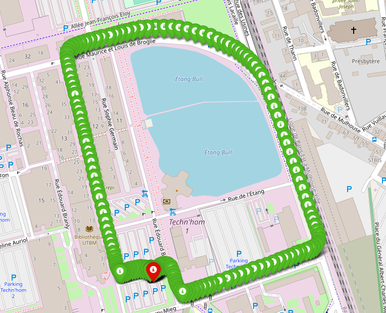
Example of visualized GPS points
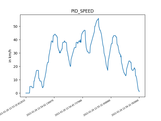
Example of plotting OBD Speed
Gettig started with code
The project uses the operating system FreeRTOS. It contains 4 tasks as showing the table below:
| Task | Priority | Role |
|---|---|---|
| Task1 | 1 | Collecting the OBD data with 1 sample/90ms |
| Task2 | 1 | Collecting GPS data(longitude, latitude, altitude, GPS speed) and IMU data (accelerometer, gyroscope and magnetometer along the 3 axes (X, Y, Z)) |
| Task3 | 1 | Collecting the OBD data with 1 sample/60s |
| Daemon Task | 3 | Writing data in SD card |
Below is a table representing the various OBD data required, as well as how often they are taken:
| Data description | OBD-II PID | 1 sample/90ms | 1 sample/60s |
|---|---|---|---|
| SPEED | 0x0D | x | |
| AMBIENT_TEMP | 0x46 | x | |
| PID_RPM | 0x0C | x | |
| ENGINE_REF_TORQUE | 0x63 | x | |
| PID_RUNTIME | 0x1F | x | |
| BAROMETRIC | 0x33 | x | |
| FUEL_LEVEL | 0x2F | x | |
| HYBRID_BATTERY_PERCENTAGE | 0x5B | x |
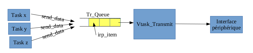
Daemon Task concept
The daemon task is structured as shown in the diagram above. Each data collected is subsequently placed in a queue, before being written in the SD card.
Lets detail the methods of the most important script files.
customized_DateAndTime.h/cpp
| Method | Description |
|---|---|
time_t StringToDatetime(char *str) |
It converts the date and time from string format to time_t type |
void UpdateTime(void) |
It updates time of the RTC |
void SetSysInstance(FreematicsESP32* sys) |
It mappes the devices in memory |
void GetCurrentTime(char* isoTime) |
It gives the current date and time in string format |
void GetCurrentGPSTime(char* isoTime) |
It gives the current time according to GPS |
int GetShiftTime(char* tm1,char* tm2) |
It returns the shift between two time stamps in seconds |
customized_SD.h/cpp
| Method | Description |
|---|---|
int getFileID(File& root) |
It returns the ID of a new CSV file |
void appendFile(fs::FS &fs, const char * path, const char * message) |
It combines the string message with the data of a CSV file |
void init_SD_Card(ObdInfoPid* PIDs, int nbr_elem) |
It initializes the SD card device and create a new CSV file during a power cycle wake |
char* getFileName(void) |
It returns the name of the used CSV file |
To save data in RTC register(ex: the CSV file name) during deep sleep, we need to attach RTC_DATA_ATTR in the declaration of the variable.
To know the cause of wake of ESP32, you should check the flag returned by esp_sleep_get_wakeup_cause().
customized_GPS.h/cpp
| Method | Description |
|---|---|
void init_GPS_dev(void) |
It initializes the GPS device and ensures the receiving a strong GPS signal in order to update the date and time |
int isDataGPSReady(int wait_MS) |
It waits for a strong GPS signal with a time out. It returns 1 if a GPS signal is detected otherwise 0 |
int FilterGpsData(char* isoTime, double* res) |
It avoids incoherent points especially when the GPS speed is more than 350 km/h this value could be changed. It calulates also the slope. It returns 1 if a slope can be calculated (It requires two successive points), 0 if it is not possible and -1 if the point is incoherent |
int AddGPSData(char* isoTime,char* p, int* nbr) |
It writes the GPS data collected previously in string pointed by p. It returns 1 if a data was written otherwise 0 |
customized_MEMS.h/cpp
| Method | Description |
|---|---|
void init_MEMS_dev(void) |
It initializes the IMU device |
void calibrateMEMS(void) |
It calibrates the IMU device |
int isDataMEMSReady(MEMS_dev* md) |
It checks if an IMU data is ready. It returns 1 if it is the case otherwise 0 |
int AddMEMSData(char* isoTime,char* p,int* nbr,int GPS_Stat) |
It writes the IMU data in the string pointed by p. It returns 1 if a data is received otherwise 0 |
customized_OBD.h/cpp
| Method | Description |
|---|---|
void init_OBD_dev(void) |
It initializes the OBD device and ensure the connection to the vehicle |
int GetOBDInfo(uint8_t pid, int* val) |
It asks the MPU of the vehicle about the value of a certain data based on OBD pid. If a data is available it returns 1 otherwise 0 |
void ErrorOBDCheck(void) |
It checks for OBD errors. For example if the engine is off |
int set_obd(void) |
It is called by void init_OBD_dev(void) to ensure connection. It returns 1 if the it done otherwise 0 |
int OBD_looping(ObdInfoPid* PIDs, int nbr_elem,int fr_max) |
It is called by the OBD tasks to ask the MPU about certain OBD pids and send data to the SD card. It returns the time in seconds for the calling task to sleep. This time depends on the evolution of the OBD speed. |
void CheckObdSpeed(char* label,char* isoTime,int val, int* res) |
It checks wether OBD speed leveled off and make ESP32 entreing in deep sleep if the vehicle has stopped. If the speed is steady, we stop writing OBD data which frequency is 1sample/90ms in the CSV file |
You can add any other OBD pids in the table declared in simple_obd_test.ino just like in the example below:
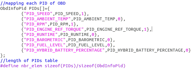
Mapping pids and their frequencies
How to improve the project ?
The board has a wifi antenna which could be used to send data to a server or phone. We can conceive a dashbord that displays the data in real time. It is possible to have some ideas by looking up in freematics github projects. We can improve the daemon task to send data via wifi.